
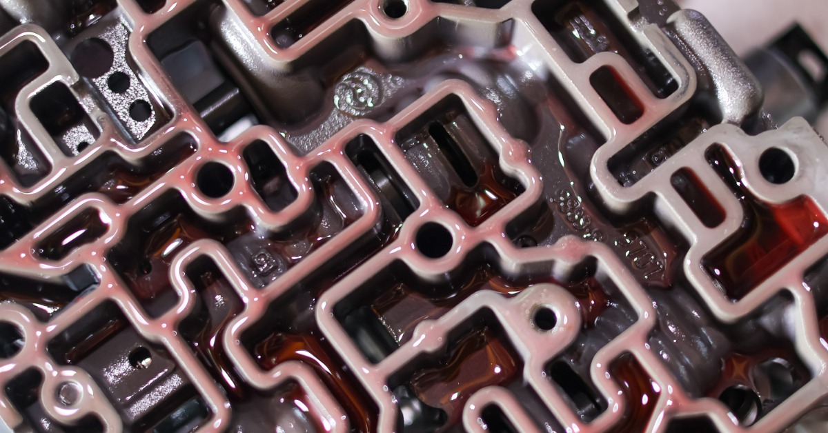
Controlled hydraulic pressure is the core of automatic transmissions. It applies to the clutches, operates the valves, and completes shifts at the appropriate moment.
Internal leaks disrupt that control, sometimes producing symptoms that resemble solenoid, clutch, or electronic faults. Detecting hydraulic circuit bleed requires a diagnostic method that examines whether a circuit holds pressure where the transmission design expects it, like wet vacuum testing.
What Does Hydraulic Circuit Bleed Mean?
Transmission fluid travels through precisely controlled passages in the valve body, case, pump, and related hydraulic components. Valves direct that fluid toward clutch circuits and other apply elements according to operating conditions. When excessive clearance, bore wear, sealing damage, or another leak path lets fluid escape from its intended circuit, pressure bleeds away before the circuit completes its job. Worn valves and valve-body bores can produce incorrect hydraulic pressure and transmission performance problems.
A small amount of designed clearance lets a hydraulic valve move and maintain an oil film, so technicians aren’t searching for absolutely zero leakage. The concern arises when wear increases clearance enough to reduce circuit pressure beyond an acceptable level. Pressure loss at a regulator valve, clutch-control valve, converter circuit, or another hydraulic location can alter how the transmission reacts under load. The exact effect depends on the circuit involved and the extent of the leakage.
Symptoms That Point Toward Bleed
Hydraulic leakage doesn’t produce one universal driving symptom because each circuit controls a specific transmission function. Delayed engagement can occur when an apply circuit takes excessive time to develop usable pressure. A flare during an upshift can appear when the releasing and applying elements don’t transition at the intended rate. Converter clutch complaints, inconsistent shift timing, or low-pressure conditions can direct attention toward hydraulic integrity.
Temperature could be another diagnostic clue. Transmission fluid thins as operating temperature rises, so excessive valve-to-bore clearance becomes apparent once the unit reaches operating temperature. A transmission that develops a repeatable hydraulic complaint after warming warrants careful circuit testing rather than an immediate assumption about electronic control.
What Wet Vacuum Testing Reveals
Vacuum testing evaluates how effectively a valve-and-bore area or hydraulic passage seals. Technicians place a test fixture over the specified circuit location, draw vacuum through that area, and observe the reading. Significant leakage prevents the circuit from maintaining the same vacuum level as a sound test area.
Transmission service information commonly distinguishes vacuum testing from wet air testing, though technicians sometimes use fluid-assisted checks when examining leakage behavior. Both approaches investigate hydraulic integrity from a diagnostic angle. Wet air testing primes a circuit with transmission fluid and introduces regulated air, making escaping fluid visible at a leak point. Vacuum testing concentrates on measurable sealing ability, making it especially useful for evaluating valve-body bore wear.
Prepare the Circuit for Testing
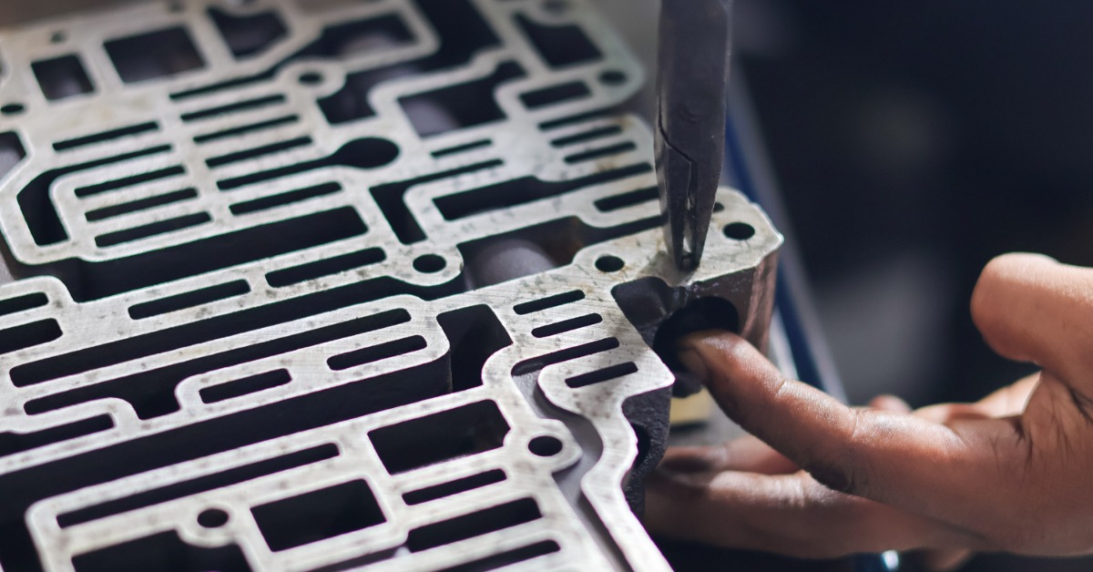
Accurate results begin with a clean component and a controlled test setup. Standard valve-body vacuum procedures generally call for a clean, dry casting because contamination, residual debris, or an uneven sealing surface could distort the reading. Inspect the test area for obvious scoring, damaged valves, gasket problems, or debris before interpreting a gauge value as bore wear.
The fixture must seal firmly against the casting around the selected passage. Test plates and sealing pads help isolate critical hydraulic areas so that vacuum loss reflects the circuit, not leakage between the fixture and valve body. Technicians should consult the test information for the exact transmission family because test locations vary among valve-body designs. Dedicated guides identify specific passages and wear-sensitive valve trains for individual units.
Test the Correct Valve Position
Valve position has a direct effect on a meaningful vacuum reading. Modulating and regulating valves don’t necessarily operate at the resting position visible on the bench. Their normal working range may place the spool partway through its travel, and wear frequently develops where the valve spends its operating time. Testing that working position gives the technician a useful picture of circuit sealing.
Move the valve according to the applicable testing procedure, seal the specified port, and allow the vacuum reading to stabilize. Record the result rather than relying on memory or a quick glance at the gauge. Repeat the same procedure at other specified circuit locations when the complaint could involve several hydraulic controls. Consistent technique matters because changes in fixture placement, valve position, or sealing pressure can produce misleading comparisons.
Interpret Vacuum Readings Carefully
A gauge number has value when the technician compares it against a relevant standard. Vacuum-testing guidance recommends developing pass/fail criteria through repeatable testing and recorded results because equipment setup and shop procedures influence readings. One arbitrary number shouldn’t become a universal limit for every bore and every transmission family.
Compare suspect areas with documented test information, known sound components, or established shop standards whenever possible. A circuit that loses vacuum noticeably compared with an acceptable example points toward excessive leakage, but diagnosis shouldn’t stop at the gauge. Inspect the associated valve, bore, plug, sleeve, separator-plate area, and sealing surfaces to ensure that the repair addresses the path of the leak.
Confirm Leakage With Additional Tests
Vacuum testing works best as part of a structured diagnosis, particularly when several components could produce the same complaint. Wet air testing offers useful confirmation. Then, escaping fluid shows where pressure leaves the intended path. Conduct this procedure for clutch and valve-body circuits, including examples where visible leakage correlates with delayed engagement or flare shifts.
A hydraulic test bench provides another perspective by charging the valve body and operating hydraulic functions under controlled conditions. Unlike a focused vacuum check, a hydraulic stand evaluates circuit operation across the assembly, though it doesn’t necessarily pinpoint specific bore wear. Combining test results helps separate a leaking valve-bore interface from problems elsewhere in the circuit.
Repair the Source of Leakage
Once testing identifies excessive circuit bleed, repair choices depend on the damaged area. Bore wear sometimes calls for machining and an oversized valve or sleeve designed to restore hydraulic sealing. Other cases involve replacing a worn valve, damaged seal, gasket, plug, or related component. The technician should base that choice on inspection and the repair method specified for the transmission rather than treating every low reading as the same failure.
Retesting remains an essential final step after the repair. Vacuum testing provides a numerical result. Technicians are able to compare the repaired area with its previous reading and confirm that sealing improved. That verification prevents a transmission from returning to service with an unresolved pressure leak hidden inside the hydraulic controls.

Use Test Results To Guide Reassembly
Successful hydraulic circuit bleed detection narrows the repair to the area responsible for pressure loss. Once testing confirms the leak path and the technician restores hydraulic integrity, reassembly should include careful inspection of the remaining wear components associated with the repair. Frictions, seals, gaskets, pistons, and related service parts deserve evaluation according to the condition of the transmission and the scope of the rebuild.
Transparts Warehouse carries automatic transmission repair kits along with individual components for numerous transmission families, including Ford and Nissan. When wet vacuum testing points toward internal leakage during a rebuild, select the parts and kit level that match the transmission application and the repairs confirmed through diagnosis. Contact Transparts Warehouse for assistance in determining which components are the best fit for your transmission.


